📷 Raytracing Project
Documenting all my learnings from creating my first raytracer/pathtracer & essentially anything new that I find out. Interested in this raytracing repository? Click here to see it on my github.
Do becareful taking everything as granted, I am human so there might be some mistakes.
This documentation is targeted towards people with all ranges of experience. I try to make it as dummy as possible but sometimes we just have to get technical so I hope it all makes sense with just a little thinking. All my learning resources are included in the github link above if you are interested in learning from the same resources I learned from.
Content
Click on any section below to go there immediately in this page
- UV Coordinates (the Hello World for a raytracer)
- Mathematics Required (Circle (2D) Intersection explanation)
- Rendering My First Sphere
- Visualize Raytracing in Unity (Small detour to see how a raytracer “looks” like)
- Shading & Rendering Multiple Spheres
- Upcoming…
to be continued…
\[x=\frac{-b\pm\sqrt{b^2-4ac}}{2a}\]UV Coordinates
The Hello World Stage

What is a UV?
UV Image or UV Texture Mapping can be interpreted as a basis for coordinates for every point in a 3D model, it is essentially an instruction to tell a texture HOW it should WRAP AROUND a 3D object. depending on how it was modelled (unwrapped), these "instructions" are created in the process of creating a 3D model, this term is called "Texture Unwrapping". however I don't specifically care about models in this context all I want is the coordinates in the context of creating a shader, & this is going off topic so back to coordinates.
What are UV Coordinates used for in shaders?
UV coordinates are used in creating all types of shaders from awesome looking shader effects & also mapping such as normal mapping & displacement mapping. It's literally the basis for every shader as we use its coordinates to specify for instructions to happen at certain places.
Simply put looking at the image on the left you can see something happening in each x/y coordinate or in this case U is the X coordinate and V is the Y coordinate. The more it goes in a certain direction the color gets stronger, X is our red channel and Y is our green channel, combining the both will give you a yellow color as seen in the top right of the image.
    //Renderer Class with Render Image Function
    void Renderer::Render(){
        for (uint32_t y = 0; y < m_FinalImage->GetHeight(); y++){
            for (uint32_t x = 0; x < m_FinalImage->GetWidth(); x++){
                glm::vec2 coord = {
			(float)x / (float)m_FinalImage->GetWidth(),
			(float)y / (float)m_FinalImage->GetHeight()
			};

                m_ImageData[x + y * m_FinalImage->GetWidth()] = PerPixel(coord);
            }
        }
    m_FinalImage->SetData(m_ImageData);
    }

    //Renderer Class with PerPixel Function (Acting Fragment Shader)
    uint32_t Renderer::PerPixel(glm::vec2 fragCoord){
	    uint8_t r = (uint8_t)(fragCoord.x * 255.0f);
	    uint8_t g = (uint8_t)(fragCoord.y * 255.0f);

	    return 0xff000000 | (g << 8) | r;
    }
How do we generate such a Image?
Here we are using a Vulkan Image to generate this for us, but the concept is the same in all instances. We first take the height & width of our image, then we loop over every single pixel in the image space and divide the current coordinates dimension with its respective image height/width.
Once we have a coordinate we send it in a PerPixel function to give us a color THATS IT dont overthink this part. More info on this function it acts as a stage in the popular graphics pipeline called "Fragment Shader". We didn't implement a real fragment shader though hence the word "act" I used previously... This is a image remember? :)
Diving into the PerPixel Function things start to explode in my brain literally. I didn't understand a thing before & im not sure if I fully understand till now since im self learning everything here. But I think I know what is going on & im going to try to explain in simple terms hopefully.
I found this on wikipedia while writing this next section its going to be crazy useful, click it to check it out, it covers how colors & bits work, all low level technical stuff. You can skip to the next part below if its boring.
Bits & Colors!
Bits are either 1 or 01 Byte is 8 Bits
1 Hex Digit is 4 Bits
uint32_t holds 32 Bits
uint8_t holds 8 Bits
RGBA is a color format that holds 32 Bits

First of all WHAT is our image?
Well I didn't show this previously but we defined our image format to be in RGBA (this was done via Vulkan so its helping a lot here) but the question still lies what is RGBA? Here I went into a mini downward spiral of curiosity since I didn't learn or do much low level programming, I wanted to know exactly what in the magic is going on specifically in the line below. Now continue on the left.
return 0xff000000 | (g << 8) | r; Looking at the beauty of this format on the left everything made sense to me now. RGBA is 32 bits each channel holds 8 bits (32 bits ÷ 4 color channels) which is also 2 HEX digits. Ever wondered in a game why when you change the color of your crosshair the max is 255? the answer is 8 bits, uint8_t is a unsigned integer (only positive) datatype that can hold a value of exactly up to 255.
return 0xff000000 | (g << 8) | r; // | is the or operator // << is the bitshifting operatorSo what is going on here? every GROUPED 2 HEX DIGITS after “0x” is a color channel except that everything here is actually reversed instead of RGBA its ABGR (LOOK AT THE HIGHLIGHTED TEXT UNDER THE RGBA32 MEMORY IMAGE ON THE LEFT). So again every GROUPED 2 HEX DIGITS after “0x” make a color channel “return 0xff000000” ff is our alpha the next 2 zeros are our blue the next 2 are green the next 2 are red. Now here comes the bitwise or operators r is being directly inserted into the memory block at the start so it immediately takes up 8 bits r is a variable of uint8_t, then g « 8 does the same thing except the « signales it to SHIFT 8 bits to the left and now is occupying the space AFTER the red channel, we then leave the blue channel empty to get the classic UV coordinate image of red & green. If you are curious on how the or operator inserts im going to quickly explain below using bits. Long story short, ORing 2 bits together will give you 0 if both bits are 0, in the case one of the 2 bits are 1 the answer is 1.
Click here to open a new tab to a wiki page of bitwise operations if you want to learn more.
//Example from https://en.wikipedia.org/wiki/Bitwise_operation
   0010 (decimal 2)
OR 1000 (decimal 8)
 = 1010 (decimal 10)
Finally, with this explanation done we can now go back to the code & return this memory block that is a uint32_t which is what the function returns. This color then gets placed into the imagedata or PIXEL whenever it gets called.
I loved this segment so much because of the low level part since I never was REALLY taught this properly & I learned this all by myself & am really happy with my progress even though its small. Hope to see you in the next section where its all just Mathematics✨
Mathematics for Circle Intersection
Line VS Ray
Where m the slope is 2 & b the offset is 5.
Ray
Both graphs are interactive click the lines to see its coordinates.
Important Notes
Vector2 refers to a vector of 2 components 𝑿 𝒀
Vector3 refers to a vector of 3 components 𝑿 𝒀 𝒁
Circle Formula is (𝒙 - 𝒂)2 + (𝒚 - 𝒃)2 = 𝒓2
(𝒂 , 𝒃) is the origin coordinate for the circle
𝒓 is the radius
Coming from Unity the two are easy to differentiate, however, some people might have different definitions for this, & it's okay just use my definitions for now. Also for this section, everything will be in 2D & can be easily extended to 3D by just introducing an additional Z coordinate.
A line is exactly what you think it is, just a long object that extends infinitely. In the context of a game engine you can tell a line to go from position X to position Y, & all it needs is 2 positions & it will draw a line.
A ray however is slightly different this time a ray dosent want 2 positions rather it wants a STARTING POSITION & A DIRECTION. Imagine this ray in your head you have the starting position set to the origin & you specify the direction to be (5,5) where would it go?
Looking at the image below the first graph, that is exactly what you would get, even though I said its a quote on quote ray under the graph its important to know that in order to differentiate between a line and a ray is that at the end of a ray you would place a arrowhead to show where the ray is pointing towards its direction. I cant show this in desmos so I placed some lines to fake an arrowhead look. Dont forget a ray contains a origin & a direction!
Quickly, the formula for the ray on the left is the following:
$$P_{xy} = a_{xy} + b_{xy}T$$ 𝑷 for any point along the line
𝒂 = origin
𝒃 = direction
𝑻 = direction scaler
Substitution: 𝑷𝒙𝒚 = (0,0) + (5,5)(1), However its also good to know that doing things this way is "bad" we should just normalize the direction vector and just multiply it by the direction scaler. Which looks like this.
𝑷𝒙𝒚 = (0,0) + (1,1)(5). With this done it should be known that if you move the origin to lets say (5,5) the whole ray moves to (5,5) & will still point towards the positive 𝒙 𝒚 quadrant (top right or 1,1) with a direction scaler of 5,5 (the tip will be at 10,10).
Testing MD & Mathjax please ignore & skip to the next section below.
\[x=\frac{-b\pm\sqrt{b^2-4ac}}{2a}\]\(x=\frac{-b\pm\sqrt{b^2-4ac}}{2a}\) \[x=\frac{-b\pm\sqrt{b^2-4ac}}{2a}\]
Circles & Square Root Magic
Solved Circle => y = ±sqrt(4 - 𝒙2)
Looking at the circle formula there is something that happens in the back that isnt too obvious, but I will make it clear here. Imagine a circle with radius 2 @ origin 0 now substituting that all in the circle formula & solving for y will give you this.
=> (𝒙 - 0)2 + (𝒚 - 0)2 = 22
=> 𝒙2 + 𝒚2 = 4
y = sqrt(4 - 𝒙2)
If you plug the final answer of y into desmos or a graphing calculator you will get ONLY the blue line of the circle as you can see on the left. In order to complete the circle from just a semi-circle you need to add a minus / turn the sqrt into a negative to get the other half of the circle to be under. flipped semi circle is y = -sqrt(4 - 𝒙2)
Magical Square Roots & The Second Semi Circle
What is the square root of 4? its 2 why? because 2 squared is 4. Now what if the 2 was -2, what is -2 squared? also 4. With this in mind now you know that square roots actually can have multiple solutions, its good to show the ± symbol before a sqrt to show that it has multiple solutions.
Rays & Circle Intersection
Now we need to find the circle intersection, you can just mouse over the graph and actually find the intersection but we need to find it with a formula & use it in our program. Lets imagine the black line to be a ray that intersects our circle but additionally imagine MULTIPLE rays coming from the bottom left and going towards the sphere in all directions. Here I’ll just make something in desmos to show what I mean real quickly.
Looking on the right is literally something really close to our raytracer we are blasting so many rays from the bottom left which we can assume in our case is the camera & shooting it forward towards all directions from a origin. Now ofcourse there are much more rays in our program this is just for showcasing. You can also see that some rays hit & go through the circle having 2 INTERSECTIONS mean while some are out of bounds of the circle and didnt manage to hit the circle while some lines just graze a singular point on the circle.
So with these intersections in mind we continue to how we find these points. Let take the ray going through the origin, the formula for that ray would be:
𝑷𝒙𝒚 = (-3,-3) + (1,1)𝑻 ///(𝑻 is infinite in the graph but its ok),
now we know the ray formula lets bring the circle formula back its:
(𝒙 - 𝒂)2 + (𝒚 - 𝒃)2 = 𝒓2 simplify it with origin 0 & move r to the left
𝒙2 + 𝒚2 - 𝒓2 = 0
This is actually enough now with these 2 formulas:
𝑷𝒙𝒚 = 𝒂𝒙𝒚 + 𝒃𝒙𝒚𝑻
(substitued in it would be 𝑷𝒙𝒚 = (-3,-3) + (1,1)𝑻)
𝒙2 + 𝒚2 - 𝒓2 = 0
Lets substitute the first equation into the second with a radius of 2, this might get a bit heavy so try to tag along.
(𝒂𝒙 + 𝒃𝒙 𝑻)2 + (𝒂𝒚 + 𝒃𝒚 𝑻)2 - 4 = 0 Which after substitution looks like (-3 + 1𝑻)2+(-3 + 1𝑻)2- 4 = 0 solving for 𝑻:
=> -32 + 2(-3 * 1𝑻) + 𝑻2 + -32 + 2(-3 * 1𝑻) + 𝑻2 - 4 = 0
=> 2𝑻2 - 12𝑻 + 14 = 0 what does it look like?
A Quadratic equation so how do we solve this? We use the Quadratic Formula (-𝒃 ± sqrt(𝒃2 - 4𝒂𝒄))/2𝒂
However, in our case we can just use the discriminant which is everything inside the sqrt, (b2 - 4ac)
The coefficients are as follows: a = 2, b = -12, c = 14. Substitute them in the discriminant we get 144 - 112 = 32.
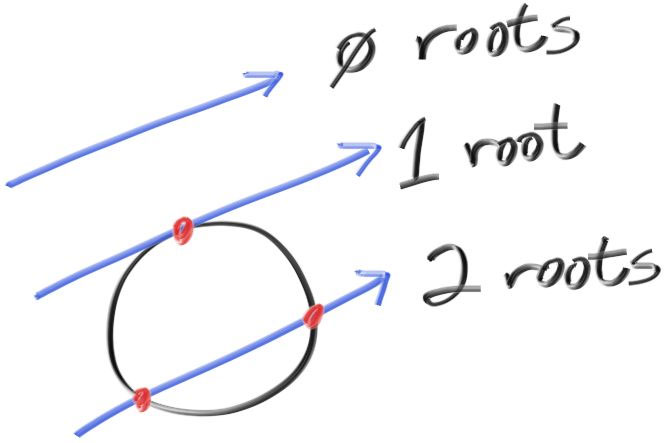
One thing the answer of the discriminant tells us is actually how many solutions there are depending on the answer, in our case we got 32 which is above 0 which means there is 2 solutions (2 INTERSECTIONS). The amount of solutions is dependent on the answer of the discriminant.
If discriminant is > 0 that means we have 2 Solutions (2 Intersects through a circle).
If discriminant is 0 that means we have 1 Solution (1 Intersect on a circles edge).
If discriminant is < 0 that means we have NO Solutions (No Intersect / Ray misses the circle).
With just this we can actually find out if any of our rays hit a sphere or not with a simple discriminant check, like so:
if (discriminant >= 0) return 0xff00ffff; //What color would this produce, from what we learned before?Another Example with magic square roots below to show the effect of the discriminant:
sqrt(4) is 2 or -2 // 2 solutions
sqrt(0) is 0 which ±0 is the same // 1 solution
sqrt(-x) is 𝒊 which any negative number under a square root has no real solutions.
But now what if you wanted to know about where EXACTLY did the ray intersect the sphere @ what coordinate? To find the exact intersection points you have to substitute all coefficients in the quadratic formula. First in our discriminant we know we have 2 solutions so that means our answer after substitution & solving should give us 2 answers which is true, the answers are 4.4142136~ & 1.5857864~. These numbers are what 𝑻 is equal to so what do we do now? Sub them in the ray equation which will yield you 2 equations -3 + 1(1.5857864) => -1.414~ & -3 + 1(4.4142136) => 1.414~ & since the x & y parts of a ray equation is the same, then the answer will be for both its x & y. The intersection coordinates are (-1.414 , -1.414) & (1.414 , 1.414), that is all we can also tell the negative version is the one closer to us or in other words the first intersection since our origin was (-3 , -3).
Check the graph above and mouse over the line intersecting the circle at the origin and check its intersection points to see for yourself.
Rendering My First Sphere
Current Ray Mapping & Issues
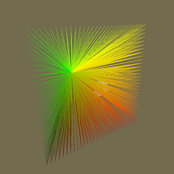
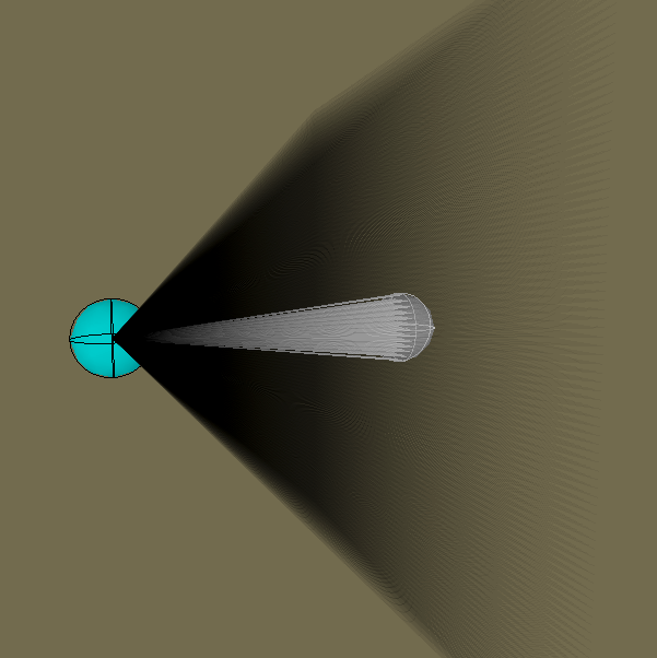
Going back to some code, we now insert a bunch of new things into the PerPixel Function. Specifically, we add all the formulas for the new math stuff we learned, we need these formulas to find the discriminant to show the sphere on our screen. However, before that even we need to fix something with our rays. Look at the image below on the right & specifically the top half of it, see how all the dotted lines are not centered and they are creating a weird slanted pyramid? that is how our ray is actually shooting out of the camera point which looks wrong. We want to have it centered like the bottom version of the right image. Left side Image also shows it but in a different angle.
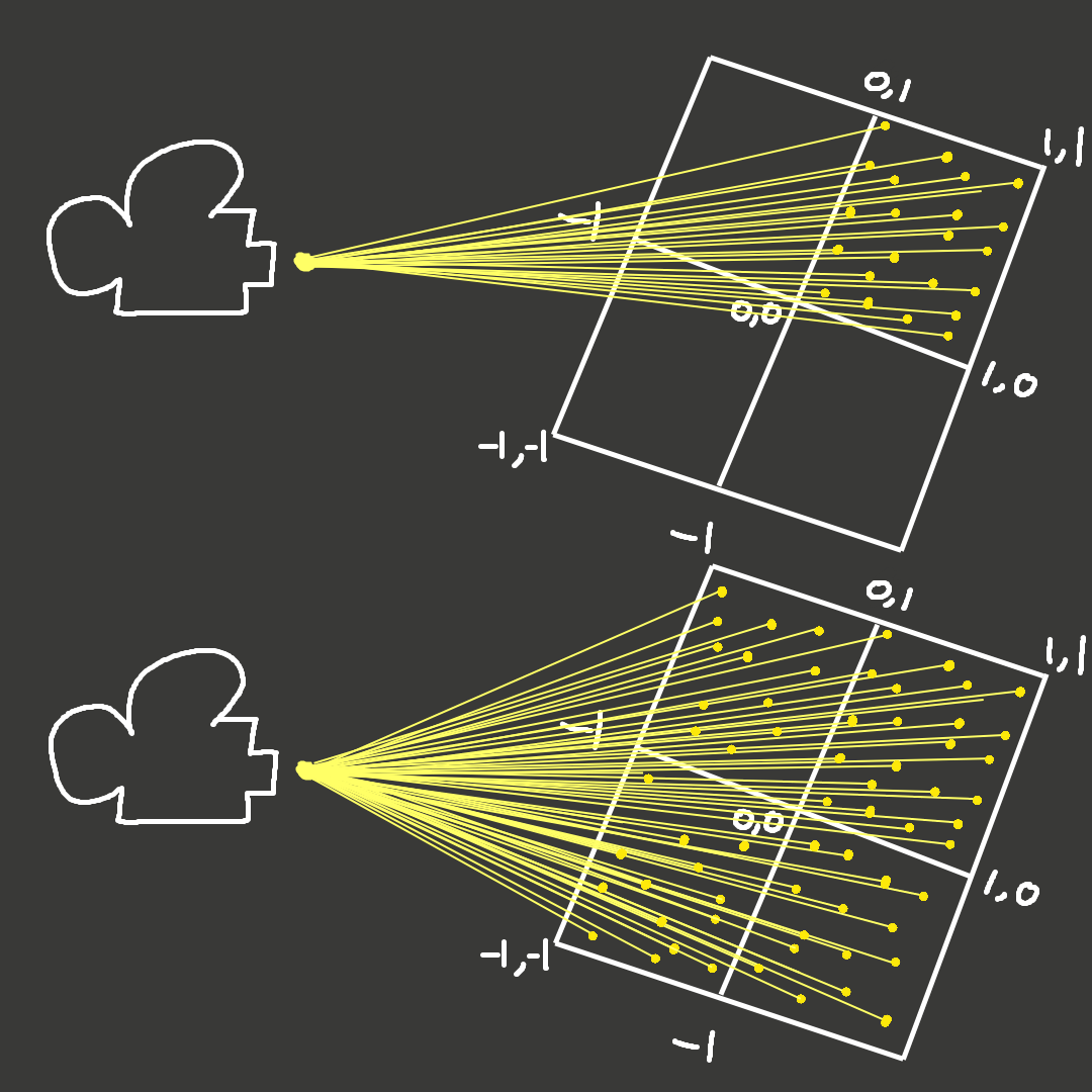
Bottom half shows how a camera should behave, where all the rays it shoots are all centered. Look at bottom half of the right image to get a better idea.
Top half shows our current rays mapped in the 0,0 to 1,1 range, this is a different angle compared to the image on the left, this should help give you an idea of why the 0 to 1 range is wrong.
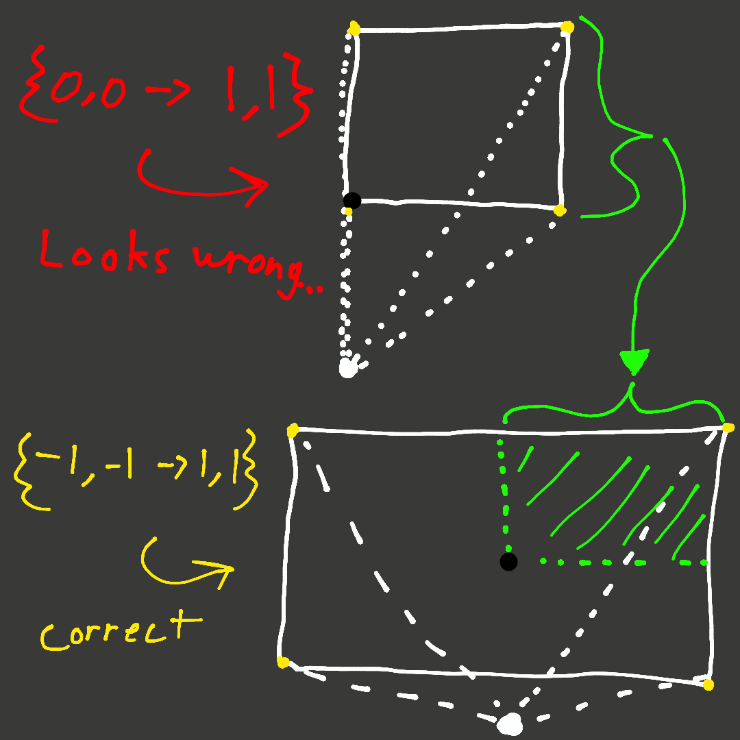
Actually just thought of extremely simple example to understand, Imagine both your arms out holding a camera & the camera is centered to the center of a picture of the Mona Lisa, now you try to take a picture of the mona lisa but your camera is mapped to the 0 to 1 range. Taking this picture, you would only see the top right “square” of the mona lisa on your picture. See them below, comparing again 0 to 1 range vs -1 to 1 range.
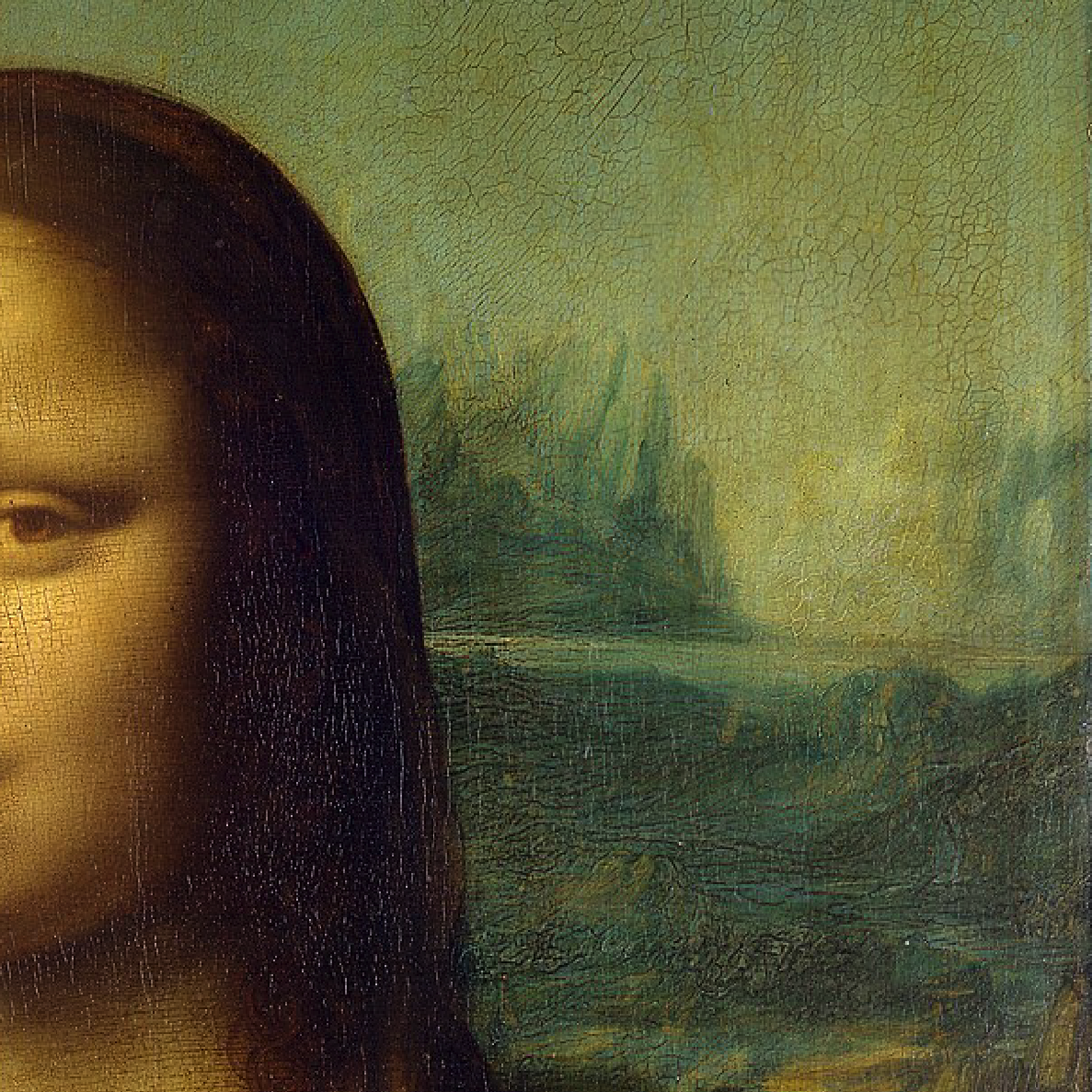
What is the mapping for this? (Mouse below for the answer)
If you said 0 to 1 you are right!
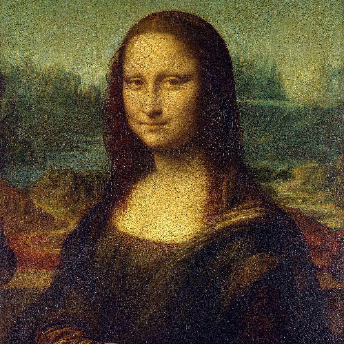
What is the mapping for this? (Mouse below for the answer)
If you said -1 to 1 you are right!
        //Renderer Class with Render Image Function
    void Renderer::Render(){
        for (uint32_t y = 0; y < m_FinalImage->GetHeight(); y++){
            for (uint32_t x = 0; x < m_FinalImage->GetWidth(); x++){
                glm::vec2 coord = {
			(float)x / (float)m_FinalImage->GetWidth(),
			(float)y / (float)m_FinalImage->GetHeight()
			};
            //====================NEW=ADDITIONS=BELOW====================
                coord = coord * 2.0f - 1.0f;    // NEW ADDITION TO MAP RAYS FROM -1 to 1
            //====================NEW=ADDITIONS=ABOVE====================
                m_ImageData[x + y * m_FinalImage->GetWidth()] = PerPixel(coord);
            }
        }
    m_FinalImage->SetData(m_ImageData);
    }

    //Renderer Class with PerPixel Function (Acting Fragment Shader)
    uint32_t Renderer::PerPixel(glm::vec2 fragCoord){
	    uint8_t r = (uint8_t)(fragCoord.x * 255.0f);
	    uint8_t g = (uint8_t)(fragCoord.y * 255.0f);
    //====================NEW=ADDITIONS=BELOW====================
        glm::vec3 rayOrigin(0,0,2); //what do you think will happen if ray origin is (0,0,0)?
        glm::vec3 rayDirection(fragCoord.x,fragCoord.y,-1);
        float radius = 0.5f;

        //solving for the quadratic formula below,
        //a coefficient under / b coefficient under / c coefficient under
        // (bx^2 + by^2)t^2 + (2(axbx + ayby))t + (ax^2 + ay^2 - r^2) = 0
        //r is the radius
        //a is ray origin
        //b is ray direction
        float a = glm::dot(rayDirection, rayDirection);             //a coefficient
        float b = 2.0f * glm::dot(rayOrigin, rayDirection);         //b coefficient
        float c = glm::dot(rayOrigin, rayOrigin) - radius * raidus; //c coefficient

        //finding out the # of solutions from the discriminant
        //quadratic formula discriminant is b^2 - 4ac
        float discriminant = b * b - 4.0f * a * c;

        if (discriminant >= 0)
        {
            return 0xffff00ff;
        }
        return 0xff000000;

    //====================NEW=ADDITIONS=ABOVE====================
    }
All new additions are encapsulated between the comments that look like //====...
Sorry for writing so much about something simple like remapping but it was something I always did without understanding why I did it, so anyways how do we fix this mapping/ray issue? After getting the screen coordinates, we multiply every coordinate by 2 & then subtract by 1. Substitute a coordinate in the coord variable below & think about the calculation mentally in your head.
coord = coord * 2.0f - 1.0f; //Maps all coordinates to the -1 to 1 range We now need to specifiy our rays & their places in the "world", so now we create a ray origin variable to set where the camera point will be at & a ray direction variable to specify which direction we are shooting all of our rays at. Now we are going to use Vector3 which means a vector with 3 dimensions XYZ (remember everything we said before can be easily translated in to 3D by simply extending everything we did in 2D by just adding a 3rd dimension Z)
glm::vec3 rayOrigin(0,0,2);      //Why not (0,0,0)?
glm::vec3 rayDirection(fragCoord.x,fragCoord.y,-1); //Try to think logically what is happening here?
First try to think of the answers that I typed into the comments before proceeding, it serves to help you understand without mindlessly reading. If our ray origin was the true origin Vector3 (0,0,0) then what would actually happen is that our whole screen will be what color is being returned from the discriminant because we are INSIDE the sphere, so what do we do? We go back 2 units (In this case 2 units can be forward but we are going to stick to flipping them since OpenGL does things this way). Going back 2 units will place the camera 2 units behind the center origin 0,0,0 which is actually where our sphere is at with a radius of 0.5. And then we specifiy a Ray Direction to go forward in the Z direction -1 (again OpenGL does things this way so we are going to follow).
Quick Rule to the Z Axis in our program the forward Z will be negative & the positive will be backwards.
Now we need to raytrace our sphere, which needs the whole quadratic equation we had going on in the previous section, to add it in the PerPixel function to get the discriminant because the discriminant needs the 3 coefficients from the quadratic equation (More information on the left, explanation on the right).
Quadratic formula we are trying to get to:
(bx2 + by2)t2 + (2(axbx + ayby))t + (ax2 + ay2 - r2) = 0
3D varient is :
(bx2 + by2 + bz2)t2 + (2(axbx + ayby + azbz))t + (ax2 + ay2 + az2 - r2) = 0
REMEMBER WE DONT CARE ABOUT THE 3RD DIMENSION. I will continue in 2D since its simpler and all we need to do to extend it to 3D is literally just add a 3rd axis THATS IT. Take the concept thats the most important thing right now. Their coefficients are like so:
a coefficient is (bx2 + by2)
b coefficient is (2(axbx + ayby))
c coefficient is (ax2 + ay2 - r2)
Getting the coefficients by doing the following below:
float a = glm::dot(rayDirection, rayDirection);
float b = 2.0f * glm::dot(rayOrigin, rayDirection);
float c = glm::dot(rayOrigin, rayOrigin) - radius * raidus;
Explanation on how we got a, b & c.
a is the ray origin | b is the ray direction | r is the radius.
We can get a coefficient by doing the standard according to the formula to the left:
rayDirection.x * rayDirection.x + rayDirection.y * rayDirection.y + rayDirection.z * rayDirection.z
But what is this line? Just a dot product, so in code we can just specificy the a to be a dot product of itself. Here is the dot product formula from MathIsFun
a · b = ax * bx + ay * by
In 3D it would be a · b = ax * bx + ay * by + az * bz
Hopefully that makes sense as to why we are using the dot product here & the rest should be self explanitory with substituting the remaining variables such as the radius and the 2 in the b coefficient.
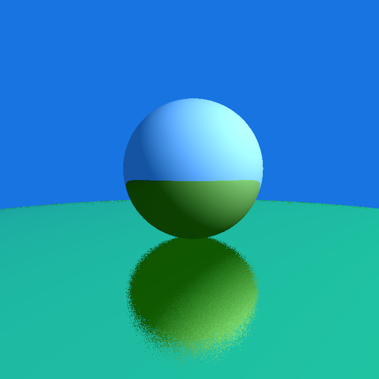
The First Raytraced 3D Sphere 🎉🎉🎉
Officially wrote my first raytraced 3D Sphere I will also include the next section to visualize this raytracer & whats going on in this program in a better light / prespective with real individual rays that you can see, I hope you stick around. 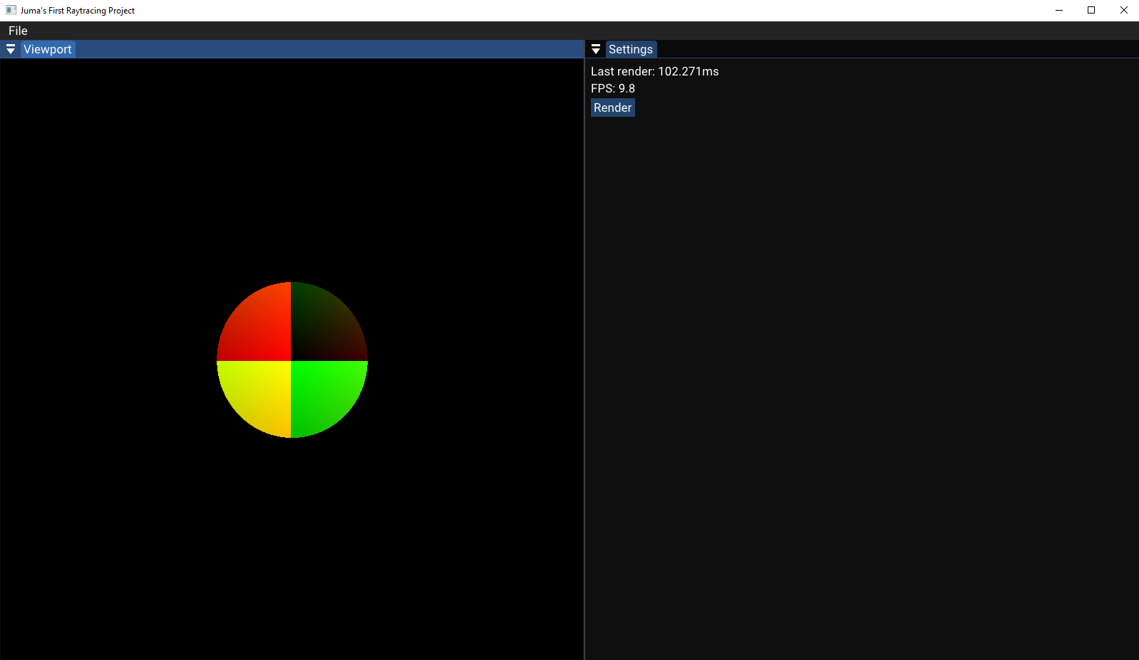
It's 3D but we can't see it because of flat shading.
color is return 0xff000000 | g << 8 | r;
Visualize Raytracing in Unity 

I tried to visualize my raytracer in Unity, here’s my take on it
Click here to access this repository on Github
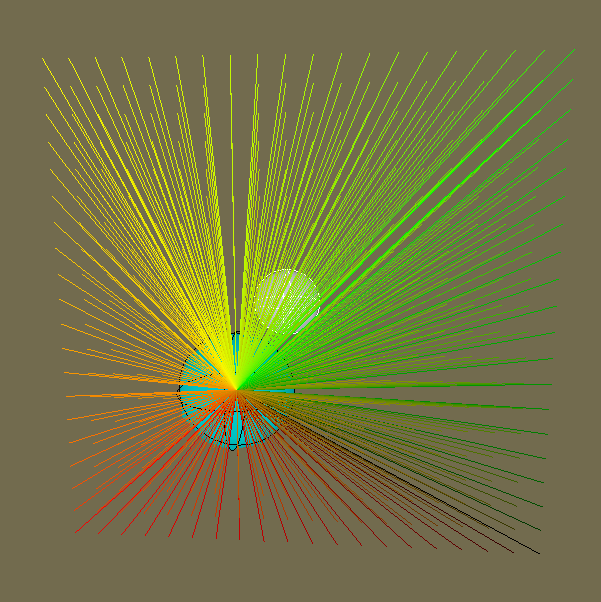
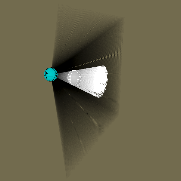
FRONT VIEW
NOT TO BE MIXED WITH REMAPPING/CENTERING COORDINATES
Also please ignore the weird drawing order that unity does with their lines
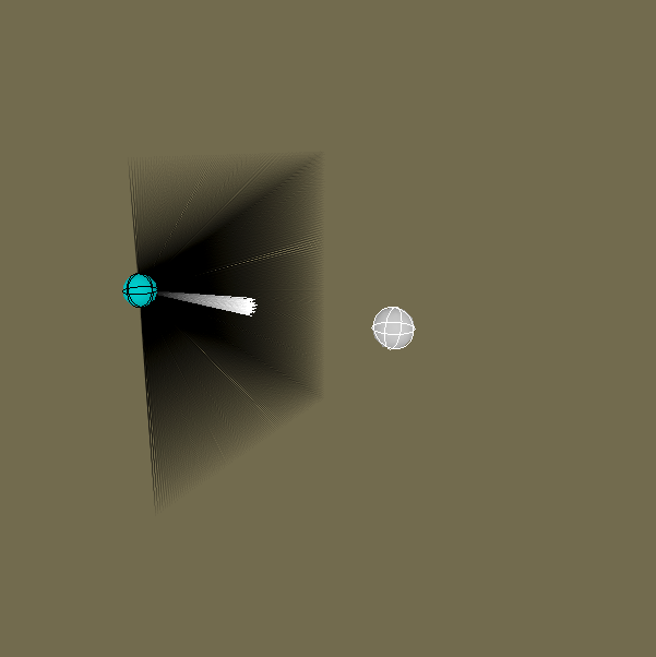
Blue sphere = point from where we cast rays & White sphere = raytraced sphere
Also please ignore the weird drawing order that unity does with their gizmos
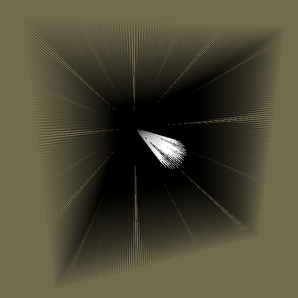
BACK VIEW
This part is to visualize the difference of coordinate mapping with (0 -> 1) to (-1 -> 1) remapping we did a before on the Mona Lisa Example
Let us begin by first talking about how to draw rays, we are going to use Unitys built in Debug.DrawLine. Since it’s a line function we are going to input 2 values first the initial position & then the final position.
Debug.DrawLine(rayOrigin, rayOrigin + rayDir * length, mainCol);Now the biggest barrier is how we create everything here that we need? I just literally import everything I had in the previous project to unity just a big copy paste block and change everything to fit Unity parameters. Check the left side section to see the code. Im not going to re-explain anything here because it’s just a copy paste from the previous section you can see how close both are.
void Update(){
for (int y = 0; y < height; y++){
    for (int x = 0; x < width; x++){
        Vector2 coord = new Vector2((float)x / (float)width, (float)y / (float)height);
        coord.x = (coord.x * 2f - 1f);
        coord.y = (coord.y * 2f - 1f);
        Vector3 rayOrigin = new Vector3(0, 0, (forwardOffset)); //Mathf.Abs(forwardOffset));
        Vector3 rayDir = new Vector3(coord.x, coord.y, -1.0f);

        float a = Vector3.Dot(rayDir, rayDir);
        float b = 2.0f * Vector3.Dot(rayDir, rayOrigin);
        float c = Vector3.Dot(rayOrigin, rayOrigin) - (radius * radius);

        float discriminant = (b * b) - (4f * a * c);
        if (discriminant >= 0.0f)
        {
            //return 0xff00ffff; abgr rgba
            mainCol = new Color(1,1,1,1);
        }
        else
        {
            //return 0xff000000;
            mainCol = new Color(0,0,0, root0Alpha);
        }
        //return 0xff000000;
        Debug.DrawLine(rayOrigin, rayOrigin + rayDir * length, mainCol);
    }
}
Also everything is flat in terms of where the rays land, so lets try to maybe visualize where our rays actually hit the sphere & make it more visually appealing.
We will do this in the next section below.
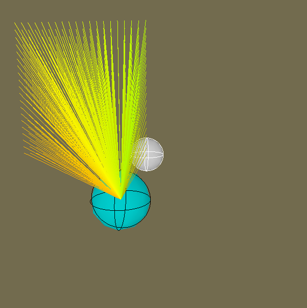
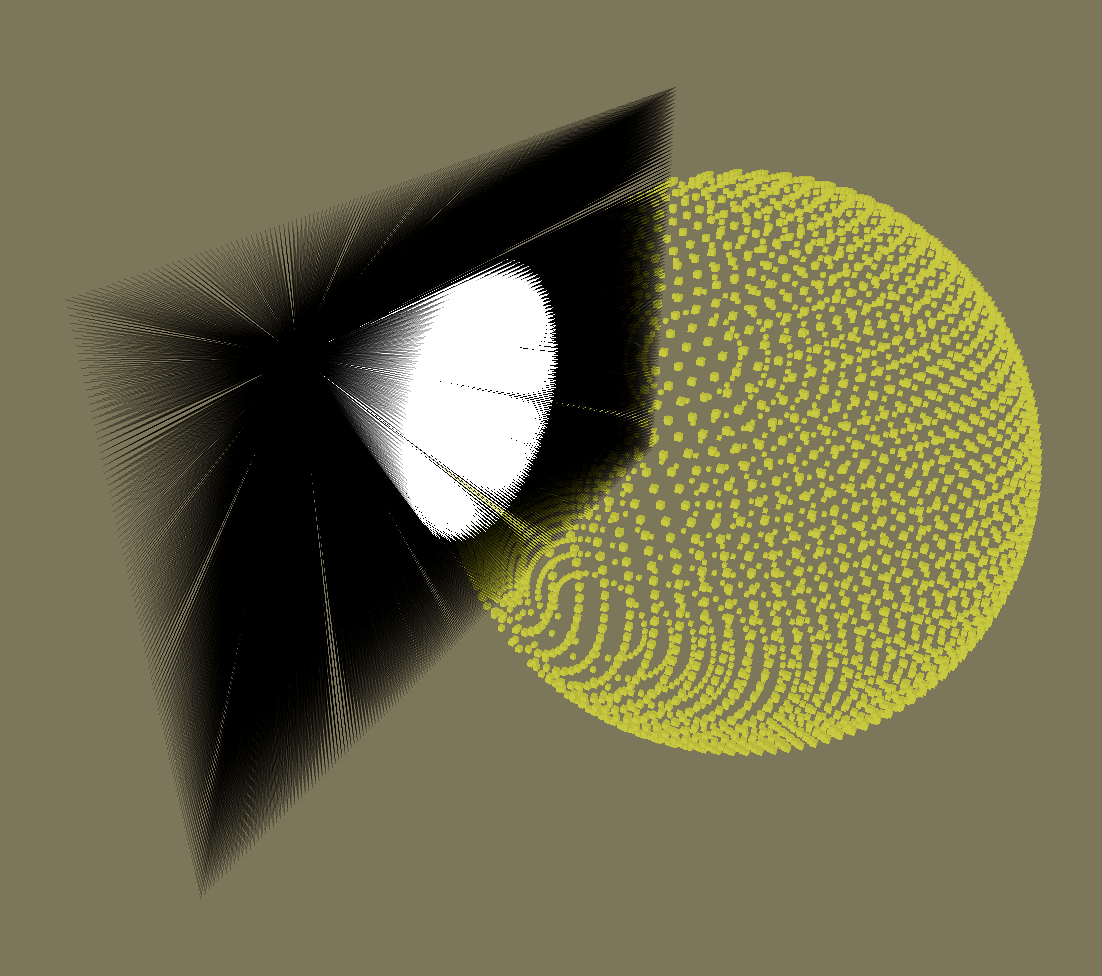
So this is basically our raytracer, literally there are rays that hit the sphere that is colored & rays that dont hit the sphere are black JUST LIKE OUR PROGRAM. This is literally the same exact thing that is going on, now this is still very medicore since we didn't address aspect ratio everything is in the 1:1 aspect ratio & increasing the parameter for height & width will just increase the density of the rays & vice versa. So now lets address how we do aspect ratio implementation since we didn't do it in our program.
I also hope that this section is already enough to see how a raytracer actually works by just blasting rays from a single point & seeing if it intersects something but yeah this is literally how it looks like in a 3D prespective compared to our "2D" like view in the raytracing project.
Diving into aspect ratio, it's very simple. We take our current width divide it by the height we get a scaler value & with this value we multiply the coordinate of the X axis with the result of the division previously. This will give you aspect ratio support, feeding in the values of height 192 x 108 width (native resolution / 10) will give you a 16:9 ratio with the amount of pixels or RAYS in our case, provided in the height & width like any real program. float aspectRatio = (float)width/(float)height;
coord.x *= aspectRatio;
Hit Distances!… or Magnitudes if you are fancy
So how do we continue on our current work to actually see where the rays hit the sphere? This part is actually pretty easy since we already did all the heavy lifting before, since we have the discriminant we just continue on solving the quadratic formula.
(-𝒃 ± sqrt(𝒃2 - 4𝒂𝒄))/2𝒂 (we already have the discriminant so it would look like this in code)
float t0 = (-𝒃 - Mathf.Sqrt(discriminant)) / (2.0f * a)
float t1 = (-𝒃 + Mathf.Sqrt(discriminant)) / (2.0f * a)
With this done we have our hit positions, however you might notice it is just a float & that is correct we just want a scalar since we can just scale the distance to the point of where we hit the sphere. Continuing this we store the hit point in a Vector3 to visualize it in our program like so.
{
Vector3 hitPos = rayOrigin + rayDir * t0;
//Ignore These
/*Vector3 normal = hitPos - sphereOrigin;
normal.Normalize();
if (!reloadHitGizmos) // Adding hit positions to be displayed by gizmos
{
hitPositionsListT0.Add(hitPos);
normalsListT0.Add(normal);
}*/
}
{
Vector3 hitPos = rayOrigin + rayDir * t1;
//Ignore These
/*Vector3 normal = hitPos - sphereOrigin;
normal.Normalize();
if (!reloadHitGizmos) // Adding hit positions to be displayed by gizmos
{
hitPositionsListT1.Add(hitPos);
normalsListT1.Add(normal);
}*/
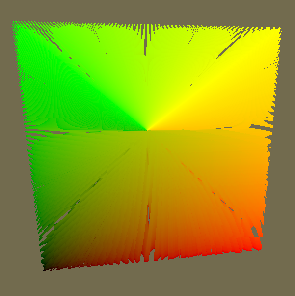
}Now we have all the hit positions on the sphere, all we have to do is now draw the gizmos, you can do it anyway you’d like since you just have to show the hitPos, example of drawing a cube at the position of the hitPos Vec3 variable will give you something like the pictures below!
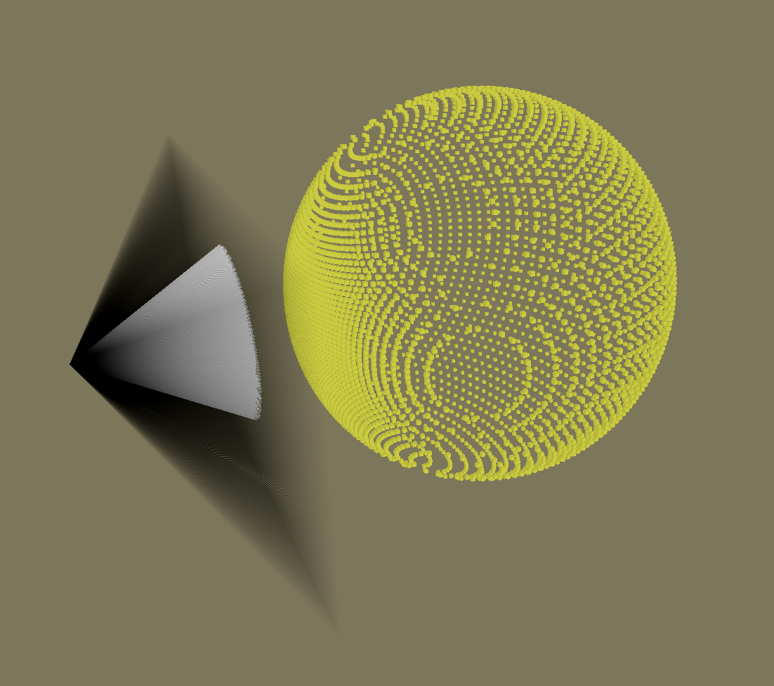
We now finally have a sphere! We can also add more stuff to this such as lighting I will quickly explain how to do it. First we need the normals of the sphere, (If you dont know what a normal is check this out on wikipedia, basically it’s a vector that is perpendicular to the surface (the hit positions in our case)) how do we get normals in this case? It’s very simple since its a sphere, but think about it we need a vector to go out from every “face” of the sphere. Since It’s a sphere imagine you blast rays from the origin of the sphere to the hit positions what do you get? Sphere normals (the ignore lines above show this calculation, ill show it again below).
Vector3 normal = hitPos - sphereOrigin;
normal.Normalize();
Now we have normals lets handle lights! Check the figure below to help yourself understand all the vector math that is going on, which is needed for lights.
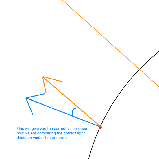
I will show this with a circle since its easier to visualize, the blue line will be our normal, the black line will be our hit positions, & the orange line will be the light direction.
Lets specify the light direction, in the image it just looks like a long line but we need explicity state its direction.
Lets imagine the light going from top left to bottom right (THAT MEANS THE LIGHT DIRECTION IS (1,-1)). Now lets compare a normal to our light direction with the dot product (THEY ARE THE SMALL LINES YOU CAN SEE AT THE IMAGE ON THE LEFT EXACTLY HAPPENING TWICE ON THE TOP LEFT QUADRANT AND THE BOTTOM RIGHT QUADRANT).
Comparing 2 vectors with the dot product will give you a value of 1 to -1 assuming everything is normalized. However, we didnt address one thing which is the problem with our light direction we actually need to flip it because of how the dot product works. Check the image below to see the current light vector and the inverted one on the left which is the correct version. Again remember the blue is the normal, orange is our light direction, black is our hit positions or the "Sphere/Circle". Images are not to scale & assume everything is normalized.
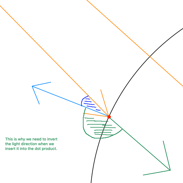
To invert the light direction we simply just prefix it with a negative sign (think of it as multiplying a vector by -1).
float lightIntensity = Mathf.Max(Vector3.Dot(normalsListT0[i], -mainLight.transform.forward),0);We use Mathf.Max to just make sure the value isn’t going under 0 since we just need the 1 to 0 range since its going to be used as a color intensity factor. With this lightIntensity variable we just multiple our final color to this scalar and we get the following below. (I extended mine to take direction from the light object you see me controlling but the concept is literally the same)
I hope that this was not too overwhelming, & if you would check this out in unity click here & download the repository to play (check the read me section for instructions).
Shading & Rendering Multiple Spheres
Click here to go back to my home page.

Juma Al Remeithi
Game Developer & Graphics Enthusiast