🌱 Shell Texturing
This post will mainly be about my YouTube video where I go over shell texturing.
Watch the video if you’d like to learn about shell texturing & how I learned & implemented it.
I will also write a YouTube script here, even though it’s probably a good idea to just keep the script private, I don’t really care, so I will make it public.
Since I want to begin learning some math notation for the future when reading about math when it comes up in shaders/blogs/articles I will include some math notation in this video so I can get some practice in.
latex.codecogs.com - Latex Editor #1 OR latexeditor.lagrida.com - Latex Editor #2. I will also use these latex editors which I found online, which even have downloads which is awesome, just wanted to share this before I start :) (Suggest #2 for writing and #1 for downloads)
Part 0 - Disclaimer
In this video I will probably make some mistakes since I’m learning a new topic, feel free to correct me in the comments about anything I say wrong.
This video’s main objective is to not showcase shell texturing but to go over what I did & learned in the #acerolafurrychallenge held by Acerola. This video will contain some math & shader terms that I might not explain from the ground up so I apologize in advance if something didn’t make sense (insert Acerola video & advise to watch it before watching my video), im trying my best to keep this video short.
I also want to emphasize that I tried doing this challenge to the best of my ability by just learning from the video instead of straight jumping into Acerola’s source code & copying code, I tried to do everything at the start by myself & only when I got stuck/finished the whole project I checked his code (it’s similar anyway since I based mine off his video explanation).
Before I begin on what I did, I will try quickly explaining shell texturing.
Part 0.5 - What is Shell Texturing?
Simply put it’s an optimized technique for rendering certain types of geometries that might be difficult to render due to them requiring high amounts of polygons/triangles where instead of using “real” geometry you fake the effect with shells (or meshes).
For example, 100 blades of grass or hair with real geometry, will require triangles for every single “strand”, the issue with this is that let’s say each “strand” will contain 10 triangles and that 10 triangles spanned throughout having a 100 blades (100 * 10 = 1000 tris already, 100 blades is nothing btw) can be potentially expensive, on top of all the physics calculations in the vertex shader & etc.
However, since computers are turbo-fast nowadays there are ways to get good real physics & graphics when it comes to hair, fur, & grass, etc. But, discussing that is out of the scope of this video.
How does Shell Texturing solve this issue?
Shell texturing uses a technique where we duplicate the base mesh of an object on top of each other while killing certain pixels on the mesh to give off a shape of exactly what we want. For example, grass & fur/hair can all be done using this method, as you can see in these pictures.
Since we duplicate the base mesh a couple of times (show examples of this on-screen from #acerolafurrychallenge) to create an effect we want like fur, we don’t create many triangles (assuming you are doing it right) like a geometry grass shader for example. However, this method is still prone to optimization issues such as overdraw, if you’d like to learn about overdraw just go watch Acerola’s video where he covers it.
Part 1 - Managing The Shell Textures
First, a C# script to manage the shell textures (I CALLED THEM “SHEETS” IN MY CASE!). This ShellTextureManager script needs to manage all of the following functions & it’s good to keep in mind this data is being sent to the GPU/Shell Texture Shader.
Initial Parameters
- Height (Manage height & spread the sheets across the height)
- Density (density of the sheets / the amount of layers)
- Color (Shell texture color)
Post-Initial Phase Parameters
- Thickness (Change the thickness of the blocky “grass” shape)
- RNG Control (Max & Min, a way to control the RNG but also gives a similar effect to thickness)
These are the parameters & functions we need to have in our shell manager to control the shell texture effect & play around with the values to find something nice. More importantly, now we will tackle each of the functions above & talk about how to do them, prepare yourself for some math.
Height
Initially, I hard coded this to test with quads but soon enough I realized I shouldn’t continue with this approach since if I change the mesh it will just look like spheres stacked on top of each other with the same scale & etc. That’s not what we want, we need to protrude the mesh along its normal to this we simply do the following.
V vector = for every vertex on the object
N vector = for every vertex normal
D scalar = distance/height (SCALAR OFFSET)
i decimal = normalized shell texture index (ACEROLA CALLES THIS THE HEIGHT BUT IM CALLING IT THE “NORMALIZED INDEX”)
VERY IMPORTANT! THESE MATH FORMULAS SHOWN ARE NOT ALWAYS TO BE SCALED 1:1 IN CODE, IT IS SHOWING THE FORMULA IN A SIMPLE MATTER. IN ACTUAL CODE YOU HAVE TO ADD THIS VECTOR OFFSET, THIS RULE WILL CONTINUE FOR THIS WHOLE POST/VIDEO.
Density
Since the Script manages the density this part is simple, in my case I have an array that stores all the shells & if I change the number of layers I have it just adjusts from the upper bound of the array, example if I want more shells I add, else if I need less I delete. These both start from the upper bound of the array in both cases. After adjusting the density you need to run the height function to fix all the new changes. Moving on to Part 2!
\[{\color{white}\forall i \in \{1, 2, ..., n-1\}, \: h_i = \frac{i}{n - 1}}\]Explanation: for all elements i in the set from 1 to n (n being our max density number or # of LAYERS) the value of height or sheet index normalized is equal to i divided by n - 1. This math notation might be a bit confusing but again as I said previously I am trying to learn math notation, so just for the sake of simplicity I will show the code version which looks much simpler.
for (int i = 1; i < n; i++)
{   //casting to a float since keeping it an int will give you messed up results.
    _SheetIndexNormalized = (i / (float)(n - 1)); //this returned value ranges from 0 to 1!
    //_SheetIndexNormalized can also be interpreted as height or h
}   //this is just my garbage naming convention that I used which helped me understand more
Finally, when you have the height calculated you just send this height to the shader & set the value in the shader to be equal to this height. Acerola did this in the shader since I guess it’s faster but I didn’t know that, but it’s okay since it doesn’t matter too much right now since we are just trying to understand stuff.
Notes: none.
Part 2 - UV & Noise
Let’s talk about randomness, since we want to create grass, grass heights are often random in the real world, so to replicate a similar setting we first need a RNG for this shader, how do we do this? NOISE. we can do this by just stealing a hashing function from Shadertoy, but in all seriousness, we just need a decently uniform RNG, which a hashing function can do pretty well.
I’m in no way a cryptographic/randomness specialized guy, but I have used hashing functions many times, however I don’t exactly understand what happens inside them, all I know is that in a hashing function, we just insert a seed & that seed will be moved & some do bit shifting in the function so that a random number will come out of it ranging from 0 - 1, kinda all you need to know, not important to understand what happens inside that much.
float hash11(float p) //hash11 I stole from shadertoy (1 input scalar 1 output scalar)
{ //p gets inserted as our seed
p = frac(p * .1031);
p *= p + 33.33;
p *= p + p;
return frac(p);
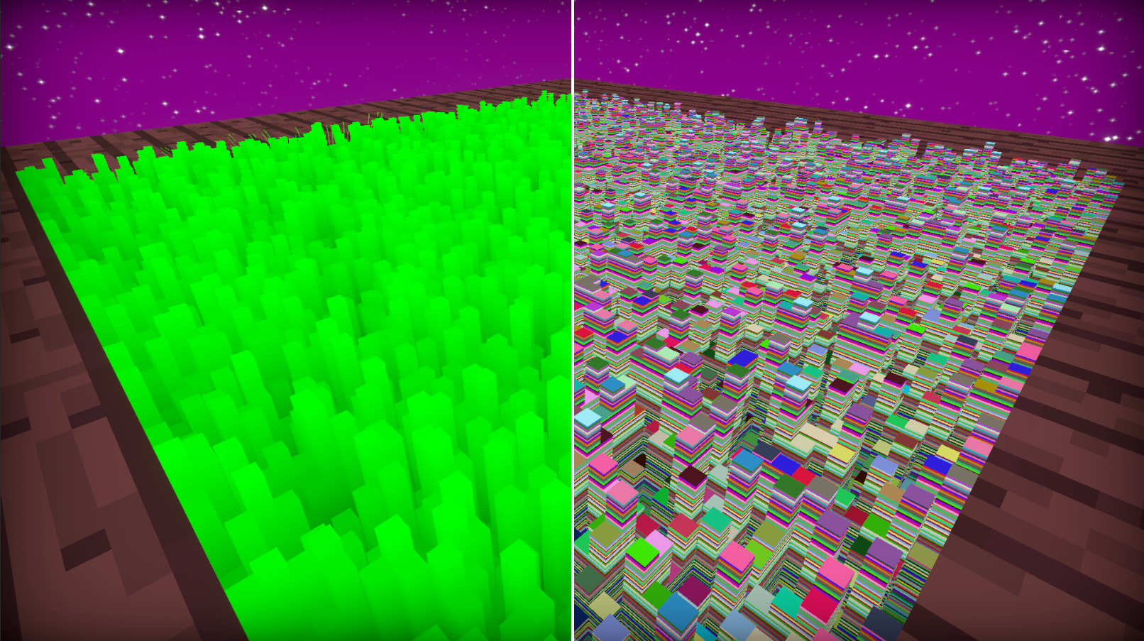
}Since we now have a black & white shell we need to address why it’s all just 1 color, that’s because its starting size is from 0 - 1 we need to resize this UV map to be larger, and to do that we just multiply the size by 100, now we have a size UV of 100x100 “blocks” that are random greyscaled colors ranging from 0 - 1.
\[{\color{white} \vec{UV^{\prime}} = \vec{UV} \times S }\]Here I came across another problem where instead of using an uint, I used a float since I never weirdly used an int type in shaders I had a spam of noise on my quad because it’s all in decimals so I never got the blocky/floor clamped numbers you would get using an uint instead of float. I was stuck on this even though I knew the issue was it being decimals while trying to understand why my noise value wasn’t magically floored. Insert typical programmer brain fart moment.
Part 3 - Blocky Grass & Fake Ambient Occulusion
Now we have randomness which means we can start to simulate grass, our way of doing this is to simply compare 2 values, the random value and the height value of the shell (both range from 0 - 1).
if the random value is greater than the height value then we display the color of the shell, & if it’s not we just discard it, quick detour, but I never knew a discard keyword existed, thought I had to use the clip function initially but discard in this case just works perfectly.
So now we have blocky grass however it’s all very green and is very boring in color, to give it some depth & make it look nice we need to add some fake ambient occlusion (real AO calculation is something I don’t understand yet & is fairly complex, insert wiki AO formula). In our case though thinking about it logically base of the grass would be darker since less sun will be able to reach the floor, and since we know our grass heights we just multiply the color by the normalized index value of the shell which is essentially the height.
\[{\color{white}AO \hspace{0.25cm} Colors = Grass\hspace{0.25cm}Color \times height}\]With this done we can now see the grass base starting with being very dark to going up to a full green color. Now the color of the grass is based on its height.
Part 4 - Thickness
To achieve sharp grass we need a way to shave off the blocks starting from the center to the outer section of the block, we can do this with a length function, however before that, we have not addressed our UVs not being properly corrected in local space.
Things will start to get a little confusing so please bear with me & excuse my garbage explanation.
UV PRIME IS THE UV RESIZED TO 100x100 (0 to 100) & NOT THE DEFAULT 1x1 (0 to 1). Previously in Part 2 I resized the UV & explained it there.
\[{\color{white} Local \hspace{0.25cm} Space = frac(\vec{UV^{\prime}}) }\]This will give us a repeating set of UVs on our plane, however, it’s not centered thus not optimal to start using our method of making a circle AT the center of the block of grass to cut the grass. To move it we simply do the following coordinate offset of the UV by adding a “* 2 - 1” to the fractional component.
\[{\color{white} \vec{Centered \hspace{0.25cm} UV} = frac(\vec{UV^{\prime}}) \times 2 - 1 }\]Now we finally have centered UVs & it’s time to get a circle so we can start cutting the grass based on the radius/length of the circle. By taking the distance of every pixel to our centered UVs we create a circle with the length function.
Length function as per Nvidia CG Documentation uses dot product
\[{\color{white} length = \sqrt{\vec{V}\cdot \vec{V}} }\]Simplified Version, squaring both xy components & adding them. Pythagorean theorem basically
\[{\color{white} length = \sqrt{x^2 + y^2} }\]Inserting the length function now
\[{\color{white} Circles = length(frac(\vec{UV^{\prime}}) \times 2 - 1)}\]With this done we now have a tiny circle repeating itself 100 times on both the x & y axis. Now all we need to do is compare the strength of the color, to the scale of the thickness we set.
if the distance from the center (strength of the greyscale) is greater than the set thickness we just kill/discard the pixel. Doing so will give you cylindrical-shaped grass. Now when it comes to my implementation of clipping the cylinder to a cone shape it’s worse since I used this with a clip function initially & am dividing & everyone knows dividing is big bad, so IMO you should stick to Acerola’s thickness implementation which is comparing if the length is greater than the thickness times the (rng - the height).
//Acerola thickness
//if the > statement is true return 1 else 0
int cone = length > thickness * (rng - height);
if(cone && _SheetIndex > 0) discard;
//My garbage thickness - originally based off clip function to get it under 0 to kill pixels
//lenMask is also INVERSED PREVIOUSLY (THAT MEANS I DID (1 - Circles) before this line)
int cone = ((lenMask * (1 - _Thick )) - ((_SheetIndexNormalized/rng) - _Thick)) < 0;
if(cone && _SheetIndex > 0) discard;Circles are obtained by doing the formula above, T is the thickness value YOU set & h is height & rng is the random value from the hash function.
\[{\color{yellow} 0 \leq h \leq 1}\] \[{\color{yellow} 0 \leq rng \leq 1}\] \[{\color{yellow} 0 \leq T \leq 1}\] \[{\color{white} Clip \hspace{0.25cm} Value = ((1 - Circles) \times (1 - T)) - ((\frac{h}{rng}) - T)}\]The Clip Value above will dictate if the pixel should be displayed or not by the 2 lines below, where if clip goes under 0 it dies else it displays. Again, I originally made it this way because I was using the Clip Function.
\[{\color{white} pixel = \begin{cases} {\color{Red}kill} & \text{if Clip Value < 0}\\ {\color{green} display}& \text{otherwise} \end{cases}}\]My thickness is based on if the value goes under 0, so if it does then it will always discard the pixel unless the value is above 0 OR it’s the first index (by first index I mean this “_SheetIndex > 0”).
Part 5 - Lighting
Lighting is fairly simple we are going to do the traditional Lambertian light model check wiki page where we reflection is calculated by taking the normal vector & the normalized light direction vector
“The reflection is calculated by taking the dot product of the surface’s unit normal vector N, and a normalized light-direction vector L, pointing from the surface to the light source. This number is then multiplied by the color of the surface and the intensity of the light hitting the surface:” - Lambertian Reflectance Wiki
\[{\color{white} Lambert \hspace{0.25cm} Light = \vec{N} \cdot \vec{L} }\]Very commonly the Light vector might be flipped in that case you just need to multiply the Light vector by -1, similarly done in my raytracer
Now the only issue is with this lighting model the dark areas are extremely dark & get no light (0 ambient light), & it’s currently unclamped which means the light ranges from -1 to 1 and negative light is weird so we clamp the light value to range from 0 to 1. Though we still have the dark areas, to fix them we can just add value to upscale it in our case this technique is called a half lambert by Valve, it’s where we multiply by 0.5 and add by 0.5, to lighten up the dark areas towards the midsection of the objects shading, this isn’t physically based anymore for obvious reasons, but we shouldn’t care since looks are more important than being technically correct as said by Acerola.
\[{\color{white} Half \hspace{0.25cm} Lambert = \vec{N} \cdot \vec{L} \times 0.5 + 0.5}\]After this, Valve squares the Half Lambert value before multiplying it in the final color calculation to see the difference between the shaded & lit areas.
Part 6 - Windy Grass & Grass Displacement
My wind implementation is not something worth talking about since it’s really simple just a sine wave with a slight offset based on the height scaled with a strength value. A “good” wind implementation would probably use something like a noise map that features noise in a way that is shaped in black & white strips while the strips are slightly distorted in the direction they are moving in. Add the noise offset & see your results, moving on to the more important thing is Grass Displacement.
Grass Displacement is currently based on a sphere shape since a sphere is the easiest shape to implement as it’s just a number (as in the radius), we also need the position of the sphere for direction calculation. Once we have this we can do our full grass displacement calculations.
\[{\color{white} \vec{V} = Vertex \hspace{0.25cm} Vector}\] \[{\color{white} \vec{S} = Sphere \hspace{0.25cm} Vector}\] \[{\color{white} \vec{Direction \hspace{0.25cm} Displacement} = \vec{V} - \vec{S}}\]Displacement Direction from the origin of the sphere position pointing towards the vertex position, since the whole word of displacement direction is a little long I will substitute it with Vector SV to signify it’s a vector going from S to V.
\[{\color{white} {Clamped \hspace{0.25cm} Displacement} = saturate(\frac{length(\vec{SV})}R)}\]Once we have the clamped displacement scalar (THIS IS NOT A VECTOR ANYMORE, I KNOW IM SAYING DISPLACEMENT BUT I THINK IT MAKES MORE SENSE THIS WAY) we now need to inverse it before we multiply it into the final normalized grass displacement vector to push them away. I will shorten “Clamped Displacement” to just CD in the next line.
Before I continue I want to address that SV is now normalized in the final Grass Displacement Vector we do this since we need to compare the value from the inversed clamp displacement. A Normalized Vector has the hat above vector SV, & normalizing is calculated by dividing the vector by its magnitude/length.
\[\color{yellow} \hat{SV}=\frac{SV}{||SV||}\]SV is normalized, in our case in code we just do normalize(SV), but I wanted to show it here since normalizing is important. I might make a post just about normalizing and how it’s used everywhere.
\[{\color{white} \vec{Grass \hspace{0.25cm} Displacement} = \hat{\vec{SV}} \times (1-CD)}\]The full formula without reducing all of this garbage looks like this (this should work if you plug it into code).
\[{\color{magenta} \vec{Grass \hspace{0.25cm} Displacement} = normalize(\vec{SV}) \times (1-saturate(\frac{length(\vec{V} - \vec{S})}R))}\]New Better Summarized Script
This is the end, you can exit from here/skip all this garbage below, since after this point is the script for the YouTube video.
Introduction
In the past week or two, I took part in Acerola’s challenge to implement a shader technique called Shell Texturing. In today’s video, I’ll discuss my experiences and everything I learned during this challenge. To add some fun, I decided to adopt Acerola’s video style, talking into a mic while using a crayon and displaying stuff on the screen to aid my garbage explanation. It’s important to note that this video is focused on sharing my challenges and learning experiences, & NOT providing a comprehensive overview of shell texturing. I recommend watching Acerola’s video first for a complete understanding (link in the description).
Disclaimer
Quick disclaimer: If I make mistakes or explain things incorrectly, please correct me in the comment section. It’s important to note that when I initially tackled this challenge, I refrained from diving into the code directly. Instead, I attempted to implement shell texturing based on my understanding from watching the video. Only when I encountered difficulties did I turn to the code. I highly recommend this approach for anyone learning something new, as it proved beneficial for me in grasping concepts. Another disclaimer: I might skip explanations for certain shader or math terms in this video. I apologize in advance if anything is unclear. Additionally, I’ll be presenting formulas in math notation, which may be challenging to read. Despite my aversion to math notation, I’ve decided to confront it for the sake of my future learning. I’ll do my best to simplify and explain these formulas using code or plain English for the audience.
What is Shell Texturing
Shell texturing is a shader technique used to fake depth and volume using Shells and 2D Textures. Commonly utilized in games to simulate complex geometries like fur, hair, or grass, and dense, thin objects such as carpets or vines, this method is particularly valuable for real-time rendering where optimization is critical. Despite some compromise in visuals, it remains a favorable trade-off, as seen in recent games like Genshin Impact. However, Shell texturing has optimization flaws, like overdraw when too many layers are involved, a topic beyond the scope of this video (I recommended to watch Acerola’s explanation).
Managing Shells
In my approach, the initial focus was on managing all the shell textures. Rather than immediately diving into shader code, I prioritized establishing functionality such as layer count and height adjustments. However, I encountered my first dumb mistake related to forgetting about normals.
Before delving into that, let’s discuss how I handle layers. I use an array to store all the layers, adjusting the array size when changing the layer count by adding or removing layers from the upper bounds of the array. The challenge arises when the shells don’t match the set height, requiring a height function to correct their heights. Regarding my initial mistake, I mistakenly set the shell offset using an upward vector instead of considering normals. While it didn’t pose an issue with quads, I knew it would become problematic with spheres, so I promptly corrected it to incorporate normals.
Now, what are normals? They are vectors perpendicular to the vertices of a 3D model or shells in this case, primarily used for shading and lighting calculations, topics we’ll explore later in this video. To set the height of each shell based on normals, one simply offsets the shell vertices by the normal vectors, multiplying them by the max height/distance value and the shell index normalized value.
\[{\color{white} \vec{V} = \vec{N} \times {D} \times i }\]The shell index normalized value is my garbage naming convention I used to comprehend height distribution within my shells. It’s a value ranging from 0 to 1, obtained through the following mathematical expression & code implementation, but In simpler terms, the Index-based Height, ranging from 0 to 1, is derived by dividing the index of a shell by the total number of shells. To reiterate, the purpose of this script is to send values to our shader (GPU), with the most crucial ones being height and density (number of layers). As a side note, instead of using the term “height,” I might refer to it as “Shell Index Normalized,” something I adopted for personal clarity, given its range from 0 to 1.
\[{\color{white}\forall i \in \{1, 2, ..., n-1\}, \: h_i = \frac{i}{n - 1}}\]for (int i = 1; i < n; i++)
{ //casting to a float since keeping it an int will give you messed up results.
_SheetIndexNormalized = (i / (float)(n - 1)); //this returned value ranges from 0 to 1!
//_SheetIndexNormalized can also be interpreted as height or h
} //this is just my garbage naming convention that I used which helped me understand moreUV & Randomness
Since my objective was grass, we need to understand what grass is, & unfortunately grass is something I rarely interact with. cut
Picture yourself at Subway enjoying a steak & cheese sandwich, glancing at a patch of grass outside. The first thing to note is that grass has random heights & varying densities, thicknesses & etc. Here we will be addressing height & ignoring everything else because we are dumb, so how do we achieve random height? Noise, how do we get noise? by stealing a noise or hashing function from Shadertoy, you can trust me on this part since I do it often & Inigo Quilez is a pretty reliable guy, the source? Trust me bro.
Now I don’t understand exactly what happens in hashing functions but what I can tell you is that whatever you put in a hashing function is called a seed & it gets moved around and sometimes bitshifted to give you a random value. The sole purpose of this hashing function is that it takes a seed and outputs a random value that is in the range of 0 to 1, we need to also make sure though that its values look equally distributed, so what does that mean?
Make funny drop table
Now I’m not a statistics guy, but if monster A drop table contains say 3 items being Asmongolds Hair, Acerolas Mic, or 500 dollars. If the drop table says Asmongolds Hair has a 99% drop chance, we can say monster A’s drop table is NOT uniformly distributed. However, if all 3 items had the same drop chance that adds up to 100%, in this case, each item would have a 33.3% drop chance, now we have a uniform distribution in our drop table.
Now we addressed Randomness our shader might just display a single color, here I came across another issue where I never in my life in a shader used an unsigned integer datatype so I didn’t get why my values were not magically floored until I realized I had a float since I normally never use anything besides a float, literally was stuck for 2 hours & experienced a programmer brain fart moment.
After fixing, we should see just a singular color across our UV that’s because our UV ranges from 0 to 1 and integers in general, floors all decimals. To fix this we simply expand our UV map & is as simple as multiplying it by a scalar. With this done we should see noise on each shell texture, & be ready to move on to coloring & shaping grass.
Blocky Grass & Fake Ambient Occulusion
To get the shape of grass, the noise or random value, ranging from 0 to 1, is important as it aligns with the height (shell index height) range. By comparing the two, if the height is less than the random value, I output a color; otherwise, just discard to kill the pixel.
Surprisingly, I this is the first time I hear about the discard keyword, since I always used the clip function to kill pixels. Quick question to the 2 people watching this video, Is it okay to use conditions in shaders? I was told they were bad so I never used conditions much, hence my unfamiliarity with the discard keyword. If you have good insights on this, please do tell me in the comment section, thanks guys!
Now that we have the grass, we are presented with another issue & its the lack of depth and its flat shaded look. To address this, a simple solution is to multiply the color output by the height (shell index height). This gives it a Faked Ambient Occlusion effect, it’s not real AO & real AO im pretty sure is much much more complicated, & is out of the scope of this video.
Grass Thickness
Explaining this section is going to be garbage & I apologize in advance if it’s garbage. Here I did my implementation on thickness but the process of killing pixels is based on clip and not discard (since I didn’t know it existed) but I changed it anyway to feature discard when I learned about it.
So how should YOU do thickness? YOU should stick to Acerola’s thickness which is a simple check of doing the following: if length from the center is > thickness * (rng - height) then discard the pixel.
Now what horrid garbage did I do? (Remember I said I used clip?) here is what I got, I compared this whole line to see if it’s less than 0, & if it is it dies, why less than 0? Because the clip function kills any pixel if the value fed to it goes under 0. cut
I’m going to go crazy I just opened the clip function on Nvidia CG docs & noticed that the clip function literally is an if statement that checks if x is less than 0 and if it’s true then discards it; I’m going to cry.
Now i’m going to try to explain WTH I’m doing in my thickness swamp. To achieve sharp grass we need to shave off each grass “block” from the center to the outer section of the block based on its length from the center to the edge, while taking into account its height for the cone shape, this is calling for the length function however we can’t directly do this as we have not done any implementation for this to work, so let’s do it now, to get a length from the center to the edge we need 2 things a centered UV that is at EACH grass block so we shave EACH grass block, how do we do this?
First, I take the fractional component of the resized UV, creating repeating UVs, then centering each UV involves multiplying the fractional component of the upscaled UV by 2 - 1, shifting it to the center of EACH “grass block”. Then finally the length function is then applied to determine every pixel’s distance from the center in each “grass block”.
With this done we should have circles in every “block” on our planes, allowing us to start shaving each grass block. Let’s go back to my garbage implementation, which is based on the clip function, what if I just plug the inverse of this length in & discard it whenever it goes < 0, we see a cylinder, but how do we change this to a cone? We need to take into account the height, now if I add a minus offset to the cylinder based on the value that comes out from the height divided by the RNG we get a cone shape. Closing out I also have these thickness variables for controlling the thickness values at certain lengths.
Now we have a grass thickness controller let’s move on, ps. don’t use my thickness method.
Lighting
The lighting here is based on the Lambertian Light model or the classic calculation of taking the dot product of normal direction & light direction, exactly done in my raytracer & toon shader previously, very cool indeed. This gives us a value ranging from -1 to 1 as the dot product does, & since negative light sounds stupid I clamp it to a range of 0 to 1 by saturating the dot product.
Small note about light direction, commonly it is given in the opposite direction and will yield wrong results, to fix this just flip the light direction to point alongside the normal direction by multiplying it by -1 or prefixing the light vector variable by a negative.
After doing all this we still have a very strong absence of light on one side to fix this we will be copying Valve’s method of a Half Lambert which shifts all values up to the range of 0.5 to 1 I believe.
Half Lambert works by multiplying the result of the dot product between the normal & light vectors by 0.5 & adding 0.5. Doing this will give you a nice light even across the areas that shouldn’t receive light, as this isn’t physical-based lighting anymore, but it’s okay since we don’t care about that. To finalize lighting Valve squares the Half Lambert value, before multiplying it by the color values to I THINK see a stronger exponential-based difference in your shaded areas.
Windy Grass & Grass Displacement
My Wind implementation is trash & not even worth talking about much, but it’s just a sine wave with a small offset & another offset based on its grass height scaled down to make it sway & give it a curvy shape.
Here is what I added to my shell textured grass & is the part I’m most happy about, Grass Displacement, let’s talk about how this formula is used to calculate displacement.
\[{\color{magenta} \vec{Grass \hspace{0.25cm} Displacement} = normalize(\vec{SV}) \times (1-saturate(\frac{length(\vec{V} - \vec{S})}R))}\]First, think about the easiest way to implement grass displacement, what is the most simple 3D shape to collide with vertices? I think its Spheres, why? because a sphere is just a single number when it comes to its size/collider (radius), using this we can easily create sphere-based grass displacement. Let’s say the radius of our sphere from here onward is 1 for the sake of simplicity.
Now, we need a direction to point the grass to go towards whenever the sphere hits the grass. To get this we do a minus, really simple:
\[{\color{white} \vec{V} = Vertex \hspace{0.25cm} Vector}\] \[{\color{white} \vec{S} = Sphere \hspace{0.25cm} Vector}\] \[{\color{white} \vec{Direction \hspace{0.25cm} Displacement} = \vec{V} - \vec{S}}\]Now we have the direction of displacment going from the sphere origin to the grass’s vertices, if we use this all the vertices of the grass should point away from the direction of the sphere, with this done we now need a way to displace ONLY the grass WITHIN the RADIUS of the sphere & leave all other grass alone that is outside of our sphere radius.
To do this we first constantly add the normalized direction displacement to the grass’s vertices but we then multiply it by a push value that ranges from 0 to 1, if this push value is 0 then assume the grass direction is Vec (1,1) & the push value is 0, we multiply the 2 together we get (0,0) not moving the grass else if the push value is 1 then Vec (1,1) * 1 is (1,1) it will then push the grass with full strength. So how do we get this push value? by doing the following.
\[{\color{white} {Clamped \hspace{0.25cm} Displacement} = saturate(\frac{length(\vec{SV})}R)}\]What is going on here? We first see the length of the vector that is going from the sphere position to the position of a vertex. We then SCALE the length proportionally to the radius what does this mean? If the radius is 1 and the length is 7 (7 means it’s far as shit), so we don’t want that vertex to be affected, this will first give you a value of 7/1 which is 7 (7 IS OVER THE RADIUS THUS IS OUT OF BOUNDS) which is then saturated to clamp to the range of 0 to 1 and is now 1, 1 is our push force… or is it?
Currently, it’s wrong because since we’re always adding an offset of the normalized direction to all the vertices (1,1) * 1 means that it will move it fully, but we did say length 7 is far and shouldn’t affect the grass! Correct, so here we inverse this push value by doing 1 - push force which equals 0 & then multiplying it by the direction which results in grass displacement value being 0, 0 means nothing & will cause the grass not to move & stay in place while doing other wind calculations.
Conclusion
If you guys watched this whole video, I just really want to thank you since it’s the first video where I did some form of proper preparation. I usually learn & practise shaders in my free time, so maybe in the future god knows when I’ll probably do something similar to this video but about another topic that I tried to bring to life. Thanks for watching!
removed old script below ignore this

Juma Al Remeithi
Game Developer & Graphics Enthusiast